

Fulldome 3D for Everyone - Part 1 / 5
The Research and Development
The Stereo Domemaster shader is the result of an innocent question asked by a friend at the Chabot Space and Science Center in the Oakland Hills, California, where I had been volunteering for just a few months.
Was it possible to create 3D movies for a dome?
I immediately thought that it would be possible, despite seeing immediately some obvious limitations. But it seemed like a good challenge to take on and come up with a workable solution.
 The first round of research about existing technology, and 3D images, in general, found that some proprietary technology existed, but adoption was very limited. Costs to enable 3D projection on planetariums were high, but in my opinion, it was the classic chicken and egg issue. As long as the production of 3D content was limited because of scarce tools availability, 3D on domes would have never been mainstream.
So, a free, open-source solution, seemed like a good idea for a start. The chosen missing production tool was a lens shader for one of the most common 3D content creation tool: 3ds Max and mental ray.
A lens shader is a plugin for MentalRay that modifies the way a camera sees the scene. The way I wanted to use it was to overcome the limitations of the common 2-cameras rigs that are used in the production of traditional “flat screen” 3D movies.
Armed with my high school level math and geometry knowledge, and after 15 years that I didn’t write a single line of C++ code, I enjoyed every single minute of those 6-7 months of research and development I squeezed out of my spare time.
The dome limitations
3D on a flat surface, like your TV or movie theater screen, is the easiest form of 3D. I didn’t say “easy”, as it still requires lots of understanding and tweaking at the capture (or rendering) and post-processing stages, but it’s a limited view area with predictable viewing positions that can be easily understood and addressed.
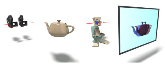
Left: Left and right cameras take images of a subject.
Right: The same images projected and filtered for each eye reproduce the 3D effect.
Both setups are horizontal, simplifying the whole process.
The dome is a different beast.
Imagine a horizontal dome, and for the sake of simplicity, just ignore the upper part, and focus on the lower edge. It might help to think of a cylindrical screen, open at the top.
It’s easy to see that a standard fixed 2-cameras/2-projectors setup wouldn’t work. If we simply extend a traditional screen and wrap it around the viewer, we would create areas where the 3D effect would be null as the cameras appear aligned.
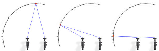
Two fixed cameras with a wide field view lose the 3D effects on the sides a the points of view align.
Even worse, in the area on the backside (not shown in the illustration above) the effect would be reversed, as the cameras effectively swap their position.
What’s the problem here? The problem is that the rendering process can create the wrap-around image in one go (through a 360 degrees lens shader), and this is a common technique in 3D renderings, but in reality, a human-looking around a panorama, will turn his head. A fundamental difference for 3D effects to work.
If we could put a lot of traditional 3D screens side by side, wrapping around the viewer, the effect would be maintained, as now the cameras/projectors pairs rotate as the viewer’s head does, but would require multiple renderings, one for each screen, or “slice”.
By reducing the width of each screen, and increasing the number of slices, edge distortions and misalignments would be minimized, and with an infinite slicing of the cylinder, we could create the perfect viewing experience.
Slicing is a common method used for real-life 3D capture of panoramic or dome images, and the number of slices needs to be something manageable. But since here we are talking about computer-generated images, reaching infinite slices is perfectly possible.
The virtual point of views technique
The solution is pretty easy, and it’s not something new. For cylindrical screens, Paul Bourke already proposed a solution. His web page is full of excellent research papers and documentation for domes and stereoscopic imagery.
My inability to read complex papers and the different goal of my shader made me set existing papers aside and come up with my own set of formulas. My findings are probably close to the ones described in Paul’s papers but added some extra control parameters that I would need to control the 3D effect on different areas.
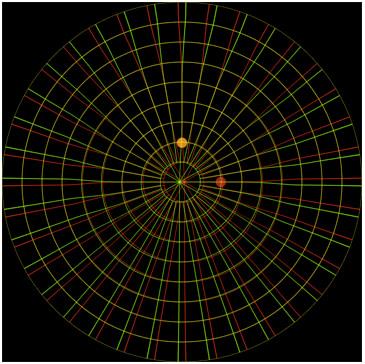
The lens shader is applied to a camera in the 3D world, and starting from the camera orientation, creates two points of views (left and right eye) that constantly rotate to look directly at the point of the dome where the pixel being rendered will be projected.
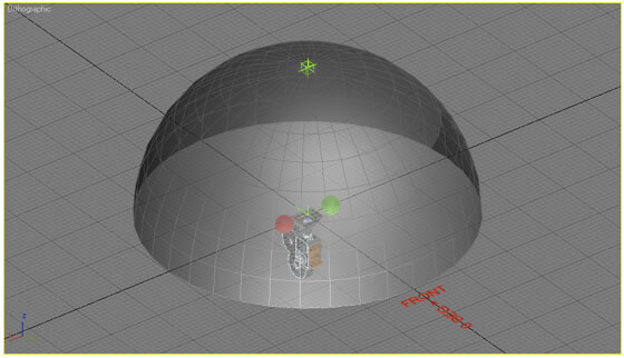
In the illustration above, the virtual points are visualized as red (Right eye) and green (Left eye) markers. This screenshot is the interactive simulator I built to develop the actual formulas for the lens shader and allowed me to visually see the effects of all parameters.
The control parameters
As we move from the cylindrical screen to a dome, we need to take into consideration a lot of other issues.
For example, a dome could have concentric seating, or all seats facing the same direction, Also, domes could be horizontal, tilted, or vertical.
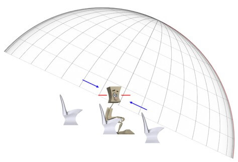
Stereo images generated for a tilted dome need to take the tilt angle into consideration to correct the convergence to the side of the dome. While the turned head remains horizontal (red lines) the Left and Right images on an uncorrected domemaster image pair would converge following the dome tilt (blue arrows).
Viewers in a dome facing the same direction will look at the top of the dome with their head facing forward but look at the back by turning it 180 degrees.
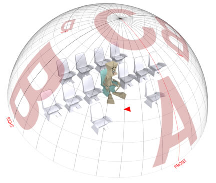
A) The easy area, where everyone looks forward, like in a standard 3D movie.
B) The sides, where dome tilt needs to be taken into account to achieve proper convergence.
C) The top area, where users will still look with their head facing forward while the default lens shader would instead try to turn the virtual cameras.
D) The back area where users need to turn their head around.
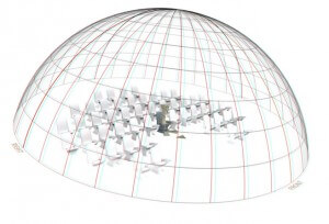
The top of the dome also poses a challenge because the virtual cameras rotate (remember the cylindrical screen example) and in the small area at the top would generate a pinch effect.
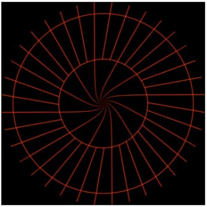
The pinch effect at the top of the dome for the right eye. The distortion on the reference grid is clear. The left eye pinch would be clockwise instead. The 3D effect in this area would be impossible for a person to see.
To solve those problems, and to allow the generation of images for all sort of domes orientations and seating layout, I added a series of maps that can control individual 3D effect parameters for each point of the dome.
The controls are three:
- The cameras separation multiplier allows the cameras to be moved closer up to be coincident to eliminate the 3D effect.
- The head turn multiplier allows to match the direction of the viewer's head and force it to look forward.
- The head tilt allows for side tilting of the head to align the eyes convergence with the most natural head orientation viewers could assume for different areas of the dome.
The head turn multiplier can be used to control the top area of the dome and eliminate the pinch by forcing the head (or cameras, same thing in this contest) to assume a specific direction.
But by forcing the head forward at the dome top, and assuming that the viewer turns his head 180 degrees to look at the back of the dome, we create an area between the top and the back where the eyes position needs to be swapped.
That would create obvious artefacts, but if we eliminate the 3D effect in that area, the transition can be achieved without anyone really noticing.
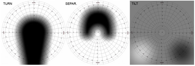
Example of control maps (with dome reference overlay).
The Turn map forces the head to look forward in the front and top areas of the dome.
The Separation map eliminates the 3D effect in the area between the top and the back to allow the camera position switch.
The Tilt map can add a side head tilt in a specific case. A 50% grey means no tilt. This map is rarely used.
Example of a reference grid rendered using the Turn and Separation maps above. The front of the dome is the lower part of the image. Note the absence of any pinch and the transition area between the top and back of the dome.
This image if for illustration purposes only, and more refined control maps can be created.
The control maps can also be used to address any other dome style. On a dome with concentric chairs, you can use them to simply eliminate the pinch at the top. On tilted dome, 30 degrees or more, maybe with reclined seats, you can keep the head looking forward even for the back of the dome.
A simple Separation gradient map can disable the 3D effect for all but the front part of the dome, providing an easy solution to create shows for all dome types.
|
|
Go to Part 2 » |
Have you liked this post? Subscribe to FDDB Newsletter
Related news
Fulldome Database
News
New Fulldome Show: The Zula Patrol – Under the Weather
A new fulldome show was just added to FDDB – The Fulldome Database, check it out: The Zula Patrol: Under the Weather by the Spitz & Zula USA Info, trailer & full length preview available.

Ondrej Kamensky
News
Fulldome Festival Brno 2021 – Tickets!
The tickets to the Fulldome Festival Brno 2021 are now available!

Fulldome Database
News
New fulldome show: Volume Visualisation Under the Dome
A new fulldome show was just added to FDDB, check it out: Volume Visualisation Under the Dome by Paul Bourke, Ajay Limaye, Alexander Mitchell and Tim Senden. Information, trailer and full length version available.
Sign up now, it's free!